
| As an example of precision machining, the gear stands as a milestone in the development of early mechanisms like clock movements. For them to function correctly, and in a predictable manner, many decisions had to be made and executed regarding their diameter, the size and number of teeth and the material chosen to fabricate it. Just imagine trying to design and manufacture a precision cog before the age of computer–aided drafting; It wasn't an easy task, and required a high level of competency in mathematics. Fortunately, creating a gear for use as a design element is much easier, and this article will show you the basic steps involved in doing just that. What follows will assume that the reader has a thorough grasp of Adobe Illustrator's tools and functions. Where there are differences in keyboard shortcuts the instructions will take the format of: (Mac Key/Windows Key + ...) |
| Pull out one guide from the top- and left-side rulers and have them cross somewhere near the middle of the page. Select the Ellipse Tool (L), and while holding the Shift + Option/Alt keys, draw out a circle starting at the point where the guidelines intersect. Command/Control click on the Eye in this layer to turn the circle into a preview outline. Lock this layer. (Figure 1)
At this point you need to do a little math. Decide how many teeth you want your gear to have. Divide that number into 360°. In the example, we're creating a gear with 20 teeth, so 360° divided by 20 equals 18°. That's the angle we'll use to set up more guidelines for the precise creation of the elements that make up a single tooth. We'll call this the "Wedge" angle. Zoom in tight on the intersection of the guidelines. If they're locked in place, unlock them (Comand/Control + Option/Alt + ; ). Using the Selection tool (V), click on the vertical guideline to make it active. Choose the Rotate Tool (R), then, while holding the Option/Alt key, click over the guidelines' intersect point to place the rotation point "target" there. When the Rotate Tool's dialogue box comes up, enter an number equal to half of your "Wedge" angle. In the example that number will be 9°. Click "Copy". |
Select the vertical guideline again, and repeat the previous process, only this time enter the same value with a negative sign before it. Click "copy" to create a new guideline that is rotated 18° clockwise from the last guideline.
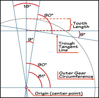
Next, you must decide how long the teeth of the gear will be. You do this by establishing the depth of the trough between the teeth. (If you want a better visual representation you could, at this point, copy the initial circle and scale it down, holding the Command/Control + Option/Alt keys to keep the center points aligned.) Pull another guideline down from the top ruler to set the trough depth. Use the Selection Tool to make this guideline active. Zoom in tight on the area where this guideline intersects with the guideline that forms the right leg of the wedge. Type "R" to select the Rotate Tool and place the rotation point where these guidelines meet. In the text field, enter the number that equals 90° minus half of the wedge's acute angle. In our example, that number is 81°. Click "OK", and you'll have a guideline that will be tangent to the bottom of the trough. This will help you keep the bottom of the trough flat. (See Figure 2 for a diagram that shows all of the guidelines used in the exercise and their relative angles) |